LogicCircuit is a free logic circuit creator for Windows which you can use to create logic circuits and also for testing the created logic circuits by running simulations. You can add all the common logical components and also various other electrical components that you usually need for creating electrical circuits and diagrams, like digital displays, LED’s, probes, clocks and so on.
Interface of LogicCircuit can be seen on the image down below. All the logical and electrical components that you can add to your logic circuit design can be added from the left sidebar. Top left corner has the standard menu. All the empty space on the right is the schematic area where you can create your logical circuits.
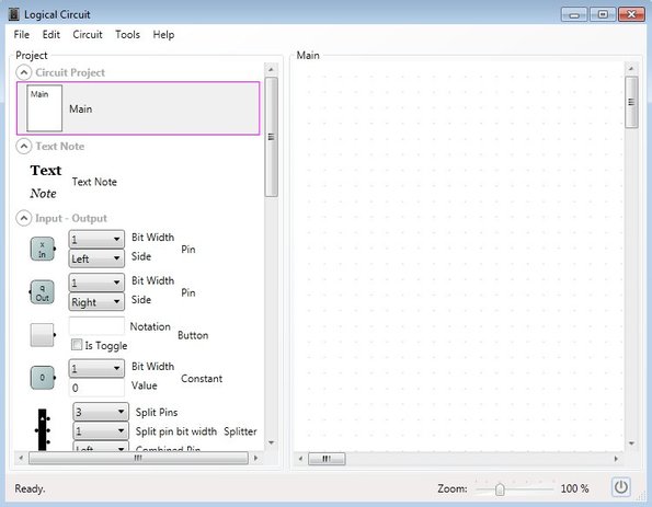
Components are added to the schematic area by simply dragging and dropping them onto it. Once that you’ve drawn logic circuit, you can then use the top left corner menu to run the simulation. It will then send reports back the results so it will be as if you’ve actually setup the created electrical circuit and tested it out.
Key features of LogicCircuit are:
- Free and lightweight: just around 1MB in size, low resource usage
- Easy to use: start creating logic circuits in just a few mouse clicks
- Has all the common logic components: Not, Xor, XNor, Or, NAnd, etc.
- Additionally it has: 7 segment display, LEDs, clock, probes, etc.
- You can also add text notes to the logic circuit that you’re creating
- Simulator: run simulations and test the created logic circuits
Similar software: Circuits.io.
In order to use this free logic circuit creator you’re gonna have to know the logic behind creating logic circuits. Without that, you can create schematics, but will they make any sense is highly questionable.
How to create logic circuits with LogicCircuit: free logic circuit creator
We’re of course not gonna go into the specifics of logic circuit schematics, because that’s not something we’re entirely familiar with, but we are gonna show you the basics of LogicCircuit usage.
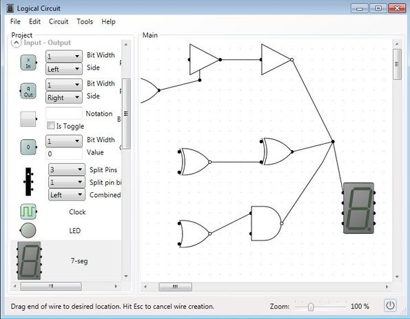
Like we already mentioned in order to add components to the schematic, you just have to drag and drop them onto the schematic area on the right. To draw lines between them left click on the end points that are coming out of the components.
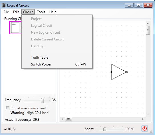
Once that you’ve created the logic circuit that you wanted, if you want to test out how it’s gonna work, select Circuit >> Switch Power from the top left corner menu. Alternatively you can select File >> Export image to export either BMP, GIF, JPEG, PNG or TIFF image of the created circuit.
Conclusion
LogicCircuit is a very easy to master application. Everything that you need is available right away from the left sidebar. If you are familiar with the specifics of creating logic circuits, then this is just the tool that you need. Once that you export created circuit design as an image, you can open it up and print out if you want. It’s perfect for both students and advanced professionals who are interested in some light logic circuit editing. Get it free.