ECD is free software to find component values of a circuit. Using ECD you can select the circuit type and then input the known component values to calculate unknown circuit’s component values. ECD is really good for university students and high school students who constantly need to solve equations and circuits.
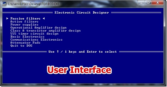
ECD provides a wide range of predefined circuits that include Active Filters, Passive Filters, Power Supplies, and many more. Later in this article, I have listed all the Circuit categories that ECD offers.
I have reviewed ECD in Windows 7. I was able to see the different component values for different circuits very easily.
Note that you require to have the circuit knowledge. In ECD you can only check the values by providing a set of values for a circuit; you can not see the circuit diagram.
Working With ECD To Calculate Component Values:
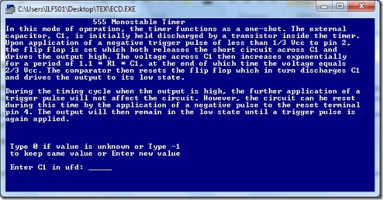
ECD is very simple to use. All you have to do is select the Text Option for Video Graphic mode and then select the type of the circuit you are working on. Input the values of prompted components and that’s all. You will have the calculated circuit’s component values instantly.
ECD also displays a nice small description about the circuit, which I really liked. Though, you need to have some knowledge about circuit diagrams.
I have listed below about the circuit types you get with the ECD. It is important that you go through the list as ECD offers a really wide range of the Circuits.
- Active Filters:
- Active Basspass Filters.
- State Variable Basspass Filters.
- Multiple Feedback Basspass Filters.
- Wien Bridge Notch Filters.
- Twin Tee Notch Filters.
- Active Low Pass Filter 1.
- Active Low Pass Filter 2.
- Butterworth-Thompson Low Pass Filters.
- Passive Filters:
- Low Pass, Constant-K PI Filters.
- Low Pass, Constant-K T Filters.
- Low Pass, M- Derived T Filters.
- Low Pass, M- Derived L Filters.
- Low Pass, Shunt M- Derived L Filters.
- Low Pass, Shunt M- Derived PI Filters.
- High Pass, Constant-K Filters.
- High Pass, Constant-K T Filters.
- High Pass, Series M- Derived T Filters.
- High Pass, Shunt , M- Derived PI Filters.
- Bandpass, Constant – K PI Filters.
- Bandpass, Constant – K T Filters.
- Band- Elimination, Constant- K PI Filters.
- Band- Elimination, Constant- K T Filters.
- Power Supply:
- Two Diode full wave regulated supply.
- Bridge rectified regulated power supply.
- Dual-Output regulated power supply.
- Transformer less power supply.
- Power supply interrupt time.
- Operational Amplifier Design:
- Inverting Amplifier.
- Non Inverting Amplifier.
- Summing Amplifier.
- Difference Amplifier.
- Class A transistor Amplifier design.
- 555 timer circuit design:
- Monostable Multivibrator.
- Astable Multivibrator.
- Basic Electronics:
- Parallel Resistance.
- Standard Value Resistor.
- Bypass Capacitor Value Calculator.
- Capacitive Reactance Calculator.
- Capacitance of LC network Calculator.
- Inductive Reactance Calculator.
- Inductance of LC network Calculator.
- Inductance of a Straight Wire Calculator.
- Inductance of a Parallel Wire Pair Calculator.
- Inductance of a Circularly arranged group of Parallel wires.
- Tuned circuit and Coil winding Calculator.
- Transformer Turns Ratio Calculator.
- Delta to Wye Transformation.
- Wye to Delta Transformation.
- Wire Size from Resistance and Length.
- Wire Size from Current Capacity.
- Communication Electronics:
- RF Air- Core Inductor Design.
- Voltage Standing Wave Ratio.
- Loseless Transmission Lines.
- Single Wire Transmission Lines.
- Two Wire Transmission Lines.
- Gaussian Pulse Bandwidth Calculation.
- Strip Line Design.
- Microstrip Design.
- dB conversion for Voltage, Current, and Power.
- Attenuator Pad Design:
- Symmetrical Unbalanced – Bridge T attenuator.
- Unsymmetrical Balanced H – PAD Attenuator.
- Unsymmetrical Unbalanced T – PAD Attenuator.
- Unsymmetrical Balanced Square – PAD Attenuator.
- Unsymmetrical Unbalanced PI – PAD Attenuator.
- Symmetrical, Balanced Square – PAD Attenuator.
- Symmetrical, Unbalanced PI – PAD Attenuator.
- Symmetrical, Unbalanced T – PAD Attenuator.
- Symmetrical Lattice – PAD Attenuator.
- Unbalanced Minimum- Loss PAD.
- Balanced Minimum- Loss PAD.
Another thing that I really liked in ECD is that while inputting the values, you can not provide values out of the range. That is, you will be provided a suggestion every time you input a wrong value for the circuit. It’s a great feature as it cam prevent many unwanted mistakes.
Features of ECD:
- Very Tiny in size
- Offers a large range of circuits.
- Very simple to use.
- No registration is required.
- Circuit Values are calculated very fast.
- Correction suggestion is shown for wrong input values.
That was about calculating circuit component values. If you require to simulate, a circuit then you can try out CircuitMod.
Conclusion:
ECD is tiny software that just works as electronics component value calculator. ECD is really simple to use and you need not know how to solve the circuit values, only the circuit description is required. However, the CGA and EGA/VGA mode did not work for me. Still, the other features make ECD a worthy software to try if you constantly work with electronic circuits (mentioned above in the article), or just learning about circuits. Based on the simple interface and effective interface I would recommend you to try it out.

