CircuitMaker is a free electrical circuit schematic maker that you can use to design complex circuit schematics. This awesome software also lets you design the PCB translation of the schematic, so you know what the final PCB product will look like when the circuit is constructed.
CircuitMaker comes with vast online resources. Your project can be saved on a cloud storage of CircuitMaker. This feature makes it possible for other CircuitMaker users to browse your project and leave a feedback. You can do the same for the projects of other users. The online repository of CircuitMaker projects is really big.
As mentioned above, your project being online can help a lot. Adding helpful comments on projects that needs a hand is a small token of CircuitMaker’s collaboration feature. You can rate and give feedback to other projects too. Help can be received in the CircuitMaker forums where you can post suggestions and discuss issues. The most important and actual collaboration feature is that you can build a team instead of applying an individual effort on the project. You can add team members as well as join a project’s team. Subsequently, you’ll be able to make changes to the project when you’re added as a team member. Another such feature of CircuitMaker includes project forking. You can fork a project to use it as a template and build an extended project.
When it comes to constructing the schematic, this free electrical circuit schematic maker has tons of real world electrical component models. CircuitMaker gives you all the physical details of the component you’re going to add. You can add these components in the schematics from the library. In addition to that, lots of components can be downloaded from the CircuitMaker website. If you’re still not satisfied then you can create your own component. You can join the components with wires, power ports, junctions, bus, etc to complete the schematic. A compiler can be run to make sure the circuit is error free.
Once you’ve completed designing the circuit schematics and PCB designs, you’ll want to have reports and outline printouts so you can start constructing the circuit. CircuitMaker will help you with generating all the specification reports and outlines of the PCB for assembly and fabrication.
Let’s take a better look at what CircuitMaker has to offer. Here are 5 logic circuit software which you can use before you start designing a real circuit on CircuitMaker.
How to Create a New Project on CircuitMaker
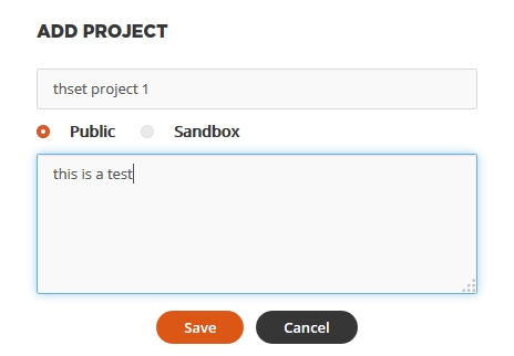
You can start using CircuitMaker once you have registered and downloaded the application. The Start interface of CircuitMaker will provide a window for the integrated online services that CircuitMaker offers. So to create a new project, click on Add new project to make one. You’ll be asked to enter the name and description of the project. In addition to that, you can choose the visibility of the project. If you choose visibility of the project as Sandbox, users online at CircuitMaker won’t be able to see your project. Your Project will be added to the My Projects tab. You can also add images, links, development stage, etc to explain the project better in the project’s description. The project can be shared on major social platforms by clicking Share.

A fork of an already created project by CircuitMaker user can be made to create a template based on that project. Click on Fork on a selected project in the All tab to do this.
On your new project, click on Open Design so you can start making the circuit schematics and PCB. To add both of them, right-click on your newly added project and select Schematics and PCB from Add New to Project menu. You’ll now have canvases where you can start designing your circuit.
How to Collaborate on a CircuitMaker Project
Comments are an essential part of communication and feedback when you’re discussing a schematic with a CircuitMaker user. To interact with someone on their project, click on the desired project. Here you can drop in a comment about what you think of the project or maybe ask them for collaboration.
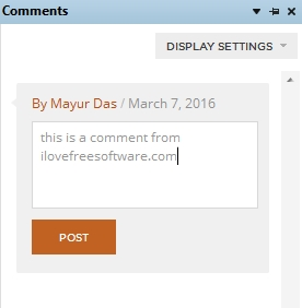
To comment more specifically about a design issue, you can click Open Design to open the project. On the view tab of CircuitMaker, select Comment from the View tab to open the comment tab. You can now enter a comment directly on a design document.

To add a team mate for help on your project, click on Team tab of your project. Click on Add New Maker and search for the name of the collaborator. You can choose whether the person you’ve added can only read the project or can edit. If you want to join a team yourself, select a user’s project and click Add new team request. You can also reply to your pending team requests from My requests.
How To make a Schematic on CircuitMaker
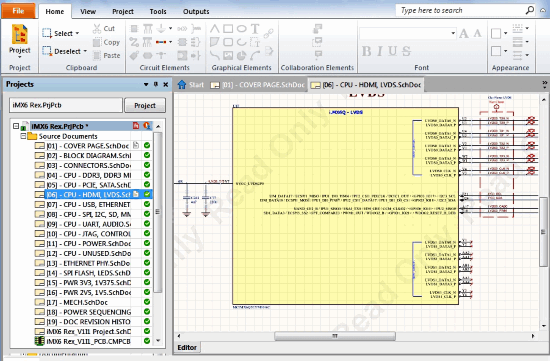
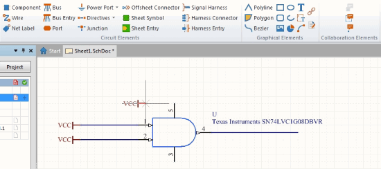
You can now start adding components to your schematic canvas, better known as the breadboard (or SchDoc file). You can add components from the Home tab. To add a component, click on Components and subsequently click Choose on the dialogue box. You can select different component libraries here. Go to Octopart and type in the name of the component in Mask. Select the component and click OK. Click on the breadboard to add the component. You can hit spacebar to change the orientation of the component. Wires and power ports can be added from the circuit elements section of the Home tab. You can also add graphical elements from the Home tab like shapes, arcs, lines, etc. To scroll around the breadboard, use the right click.
To design the PCB version, go to the PCB tab of the project. From the Home tab, click Project> Import Changes From project_name. The corresponding PCB structure of your breadboard schematic will be added. You can add extra design elements from routing and place sections of the Home tab. The Tools tab will help you with distances, autoroutes between the PCB elements.
How to Check Errors in the Circuit on CircuitMaker
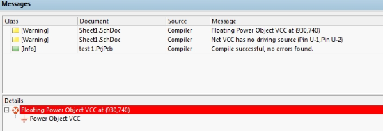
Once you have completed designing the schematic, you need to make sure that the circuit works. To do that, select the SchDoc file of the project and select Home>Project>Compile. You’ll receive the errors (if any) at the message tab at the bottom of the interface.
How to Generate Reports of the Circuit on CircuitMaker
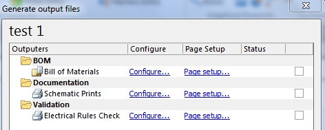
The final nail to this designing process is the generation of reports with which you’ll construct the circuit. Go to Home>Project>Generate Outputs. Click on the schematic file and you’ll be prompted to generate lots of reports such as Bill of materials, documentation, fabrication, assembly, etc. Clicking on Generate will generate a zip file of ll the reports that you can save on the desktop.
Final Words
CircuitMaker is a complex software to design complex circuits. Designing circuits has never been so easy with all the real world models you can use.Without saying much, I award this software 4.5 stars based on the vast resource available on it and the complexity of using this tool.
Get CircuitMaker here.
If you have a better alternative to this software, do tell me in the comments!